Composite Sandwich Core

This page will attempt to shed some light on the mechanics of composite sandwich panels. The main points will illustrate:

  •  the structure of a 'Composite sandwich panel'
  •  the role of the skin and core in resisting loads
  •  the distribution of forces in such panel (bending only)
  •  why composite sandwich cores
  • are stiffer and stronger than the same weight single skin panels.
  •  examples of 'modes of failure' and buckling in composite core panels


  This page is intended for those who do not have any engineering background but would still like to get a peek at the inner workings of sandwich cores.
Derivations of Flexure formulas, Moments of Inertia and other complexities
are beyond the scope of this page. A lot of assumptions are made for the sake of simplicity. All cross sections are symmetrical about a neutral axis(centriod) and the material is subject to pure bending(flexure).

 
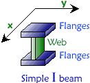
The best way to visualize the structure of a 'sandwich core panel' is to use the analogy of a simple "I" beam. (see above)
Like the 'I' beam, a sandwich core panel consists of strong skins (flanges) bonded to a core (web). The skins are subject to tension/compression and are largely responsible for the strength of the 'sandwich'. The function of the core is to support the thin skins so that they don't buckle (deform) and stay fixed relative to each other. The core experiences mostly shear stresses (sliding) as well as some degree of vertical tension and compression. Its material properties and thickness determine the stiffness of such a panel.


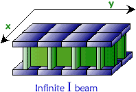
Unlike the simple beam, which is designed to withstand stresses mostly along the x axis and bending about the y axis, the sandwich panel can be stressed along and about any axis laying in the x-y plane. The implication is that such panel can extend 'infinitely', forming a strong and continuous self-sustaining plate or shell such as a wood strip kayak. No reinforcing elements are needed because they are already built into the structure.


The Core


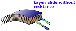
The easiest way to illustrate how the core supports shear stresses is to take a deck of cards or a telephone book and bend it. You will notice how the individual layers slide or 'shear' past each other.

Now, suppose that the sheets were all glued together. The pages are no longer free to move and the deck becomes very stiff. At this point, the only way the deck could bend is if the layers on the 'tension' side of the 'neutral axis' (red dashed line) stretched and the 'compressed' side squeezed together.


  This picture illustrates the shear in a weak core such as the unglued deck of cards or a sheet of elastic material like rubber.
The skins experience very little stress because the core deforms easily. Such cores are said to have low 'Shear Modulus of Elasticity'
 
Materials with very low Shear Modulus are unsuitable as structural cores because they cannot withstand shear stress. Boats made with such cores would be weak, excessively flexible, and easily deformed. This would defy the whole point of this construction.


  The core in this illustration would be the equivalent of the deck of cards glued together. The material resists shear (high Shear Modulus) very well. Note that the sections throughout the core are perpendicular to the neutral axis (dashed red line).
This means that the 'layers' in the core resists sliding (shear deformation) and the core and skins are forced to stretch and compress.
 
Skins made of material of high 'Modulus of Elasticity' are best used in conjunction with cores of high 'Shear Modulus'. This balance is important so that neither material fails long before the other is stressed to acceptable level.
For instance, strong Graphite or Kevlar skins bonded to a 'Styrofoam insulation' core would be a complete waste because such 'Low Shear Modulus' core would always fail long before the skin could be stressed to 1% of its potential strength. Of course, for this reason Styrofoam is not considered a structural core material.


As a note of interest; 'End-Grain Balsa wood' (Balsa is the stuff used for model airplanes) makes for the stiffest and most shear resistant cores known in boatbuilding. It also shows superior compressive and bonding strength to the skins. Of course, it doesn't mean that it is the best choice in all situations. Some cores are less stiff which makes for better impact absorption.
The point here is that despite advances in material science, the 'Good old wood' is still up there with the most sophisticated materials used today.


As far as cedar wood strip core is concerned, it has its own unique advantages that no other core has.

  •   It is cheap (commercial cores are notoriously expensive)
  •   It is self-supporting (NO other core is able to form fair compound surface when wrapped over a mold with 12" to 18" station spacing). All commercial cores need close spaced forms or solid surface plugs so that they don't sag.
  •  No special skills or tools are required to build a professional looking kayak with wood strips.

    For this reason, wood strips are the ultimate core material for prototyping and builders wanting 'cheap & quick' boats. The Wood Core Kayak page goes into more detail about its virtues.


  Now back to the cards. The deck of cards is only made of weak paper and given enough bending force it would crack and break. The cracking would begin at the surface and on the side that experienced tension. This failure is an indication that the stresses at the surface exceed the breaking (tensile) strength of the paper. Intuitively, it also shows that the largest stresses are confined to the surface of the deck.

To relieve the high stresses at the surface, a stronger skin must be bonded to the paper. The result is a panel 'composed' of different materials, each with its unique physical properties, thus a 'composite sandwich core'.


The Skin
 

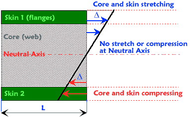
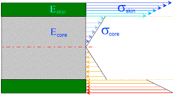
This drawing illustrates a profile cross section through a sandwich core panel. The bending causes the sandwich to stretch above the 'Neutral Axis' and to compress below the axis. The neutral axis or neutral 'plane' in real material experiences zero stress and strain.
The original length of the relaxed panel is "L".

As the panel bends, both the core and the skin elongate and shrink linearly (for simplicity) from the neutral axis. The thick black line represents the new section of the panel after bending. (very exaggerated)

Since the skins are firmly glued to the core, both the core and skin will stretch the same amount where they bond together.

  Now, the important thing to keep in mind is that even though the materials stretch equally at the skin/core boundary, they both have completely different physical properties and therefore will react differently to this elongation.

In engineering terms the ratio of the elongation to the original length is expressed as 'strain'.

The equation           means   


  Knowing the strain, it is now possible to find the stresses in both the core and the skins.

It is important to realize that the 'stress' in a three dimensional panel applies to the entire face of the section. The drawings here represent only 2D 'side view'.
This is OK since stress can also be defined as 'force per area', which means that we can think of the arrows in the drawing below as force applied to individual strands or a slice of the sandwich.

  The equation below shows that Strain multiplied by the material's Modulus of Elasticity equals Stress.

The equation           means   

  Now, you will notice that the force (arrows) acting on the skin are far larger than on the core. This is because the fiberglass skin has a large Modulus (E =10,000,000 psi) but the core such as wood has Modulus roughly six times smaller (E = 1,700,000 psi). So, equal strain at the boundary multiplied by larger Modulus will produce larger stress in the skin.
The discontinuity of the stress at the skin/core boundary is a clear indication that the fiberglass is absorbing far more tension and compression then the core. The same applies to the simple 'I' beam.

So far, it has been only shown that bonding a strong, tensile material to the core will relieve it of a lot of stress yet make the entire sandwich core stronger.

The real advantage of the sandwich core can be only made clear by comparing it to a single skin fiberglass, subject to the same bending force.

  In order to do this comparison, one more principle must be clarified:

The Applied bending force (Moment) produces internal reaction forces in the panel (the blue and red arrows) that counteract such bending. Since there is no acceleration in statics problem like this, it just happens that the sum of the internal forces(moments) must be equal to the applied bending force(moments) . In engineering terms, the forces are in 'equilibrium' or balance.
This sum of internal forces is also graphically equivalent to the area covered by the 'force arrows'.
Moments are defined as force x distance (arm) and represent bending only, as in this case.


Now, let's take this single skin fiberglass below and compare it to the sandwich core. The thickness of the panel is equivalent to three skins of the sandwich. In reality, the solid fiberglass panel would have to be far thicker to have acceptable thickness and stiffness but for the sake of the example let's say it is three layers.
The main point to take into account is that this lay-up will be as heavy or heavier than the sandwich. This is because the density (lb/in^3) of the skins can be 3 to 6 times that of the core.

Since the fiberglass is subject to the same bending moment as the sandwich, the area covered by its force arrows is also the same. It may be of different shape because the entire panel is made of 'homogenous' material but the sum of the internal reaction forces is identical!


Finally, compare the length of the longest arrows on the sandwich and the fiberglass panel. The fibers in the surface of the fiberglass panel are stressed far more (max. stress) than in the sandwich.

The conclusion:

  • Even though both the sandwich core and the fiberglass are subject to the same bending, the surface fibers in the single skin fiberglass are stressed more thus they will also stretch more. The skin will mostly bend or break. The panel will be far less stiff and strong than the sandwich.

  • Conversely, if the single skin fiberglass is assumed stiff enough, it can be substituted by much lighter sandwich core panel. In order for the maximum stresses (longest arrows) to be equal, far thinner and lighter skin is required in the sandwich.
.
  Examples of 'mode of failure' in a sandwich core panel

The cores in this case are not structural but serve as a good example of how sandwich cores fail and what happens when the mechanical properties of the skin and core do not match.

  A composite sandwich panel is bent and the skin buckles. In this instance, the core separated close to the skin-core boundary indicating that most of the stresses are concentrated here and that the core could not withstand tension.
  A similar example of buckling. Here the skin crushes the panel indicating poor compressive strength of the core. The direction of buckling (crushing vs. separation) depends on the curvature of the panel, its stability and applied forces.
  A panel subject to transverse sheer experiences complete failure of the bond between the skin and core.
 
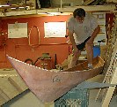
Here is an example of 5mm plywood sandwich core buckling under compression. The kayak hull is only supported at the ends. It will of course be reinforced by the addition of the deck later, but the thing to note is the mode of buckling. This behavior is typical of developable surfaces. A developable surface is formed by wrapping a 'flat' 2D sheet' around a cylindrical or conical body without stretching. So, all cones and cylinders are developable. Because such surface can be 'wrapped' and 'unwrapped' it will also be weak in that plane of bending (as evidenced in this kayak panel). Notice that the 'ripples' in the plywood run in the plane (parallel) in which the kayak side wall is bent. The way to reinforce a developable monocoque surface is to either force it into a non-developable or 'compound' shape (by stretching and twisting) or to subdivide the surface into smaller 'facets' that do not form a developable surface as a unit. This happens to some degree by the addition of the deck. A good example of this principle can also be found in Geodesic structures which assume compound shapes but which are made solely by using developable building blocks (triangles, pentagons, and other polygons). Spherical and hyperbolic surfaces (horse saddle, an egg, sphere) are examples of non-developable surfaces which are considerably stronger since they cannot be easily 'flattened' or distorted without stretching a part of the structure. This property is definitely 'a plus' in compound wood strip kayaks which are far less likely to buckle to this degree under the same amount of stress.


Modulus of Elasticity

A material with the highest 'Modulus of Elasticity' will stretch the least when subject to a given amount of force. For example, a 'carbon' fiber will stretch less than the same size fiber of 'fiberglass' given the same amount of tensile force. Thus, carbon fiber will have higher Modulus of Elasticity.

Modulus of Elasticity (E) and the related Shear Modulus (G) are unique to every material and are only few of many factors that determine the suitability of the skin and the core in boatbuilding.


To Wood Core Kayak


Home Kayak Designs Kayak Shop Materials Kayak Gallery About us
Building Manual Plans Sandwich Core Wood Kayak Order E-mail
Epoxy Test Abrasion Cloth Rudder Resources Choosing Kayak Guestbook

If you notice any problems with the site (i.e. error links, missing images) please, let me know. Thanks

Mail:
Vaclav Stejskal
58 Wood Ln.
Acton, MA 01720
           USA
Tel:  781-481-9261

E-mail  

© 1999 - 2024 Copyright Vaclav Stejskal
All rights reserved

Last page update: 9 May 2024