|
| HOME |
|
Here are the schematic drawings (amateurish but I hope clear enough) of
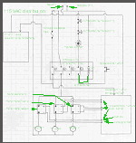
the wiring on the MadVac. Image 1 shows the 115VAC distribution in the system.
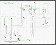
Image 2 shows the detailed wiring of the power supply (the rectangle in
image 1 named "power supply"). The specifics of the wiring between
the breakout board and the Gecko drives is well documented in the Gecko
and Campbell/Collins breakout
board manuals. You can download them from the websites. Take a look at the large picture of the breakout board on the controller page to see how I have it wired on my machine. The wiring diagrams shown here are quite general and can be used on small and large systems using stepper motors as well as servo motors. The difference in wiring between servos and steppers is only between the breakout board and the drives but the power supply and the 115VAC systems are the same otherwise. The schematic may potentially contain mistakes. For information purposes only. Use at your own risk! 75 Volts of DC is quite deadly. |
|
 Image 1 |
Image
1 - The main feature of this setup is the four
pole relay (DigiKey -Z1036-ND -$49?) which acts as the main system switch,
turning on three separate zones and shutting off everything when an emergency
stop button is hit. Contact 1 on the relay controls the 115VAC supply for the steppers which passes through the power supply to Gecko drives and also a 115VAC line to the breakout board. The schematic shows only one 115VAC supply but I power the routers and the p.supply/b.board from two separate lines to reduce voltage/current drops when the router/vac kicks in. The line is additionally protected with 12amp resetable fuse (DigiKey) Contact 2 powers the router spindles and the dust vac through the three solid state relays. The solid state relays (MPJA $6.95ea) are 25A rated at 24-280VAC SSR 3-15VDC CONTROL . The 12VDC signals to the relays come through the breakout board initiated by Mach2. Contact 3 (optional) sends E-stop signal to Mach2 when the relay opens on e-stop. This is a risky move to put logic voltage on the same relay as 115VAC but I have had no noise problems and as long as the the wires are separated it seems to work fine. See circuit with parallel port pins on the breakout board - I had to solder this on the underside of the breakout board. The new boards have a socket for this already I believe. Contact 4 contains the main system switch (normally open, momentary - AutomationDirect) which turns on the whole system by energizing the relay coil and the circuit also completes the E-stop circuit with two E-stop buttons (Automation Direct). When the system power button is pressed, current flows through the button to the relay coil which closes all 4 contacts. This action enables the current to flow from the other direction through the e-stop switches, the relay and through the coil even though the momentary button is already released. This "self latches" the relay through the "loop". Since the e-stop switches (one is on the machine frame of Madvac and the other on the front door of the controller) are normally closed, the circuit is complete and the system is on. When either of the e-stop buttons is pressed, the self latch circuit is broken and EVERYTHING shuts off. Signal is sent on contact 3 to mach2 to let it know of the condition and Mach2 will stop sending pulses and needs to be reset as well. This setup makes the e-stop on the controller also the OFF switch for the entire system. |
 Image 2 Here is a PDF file (I have downloaded somewhere) with a nice Camtronics servo diagram. This is another variation of the controller theme. |
Image
2 - The power supply ($300 CNCKits)
is another "layer" in the system with its own three position toggle
switch. In the mid position of the switch, (circuit A) current flows through
the controller case cooling fan, the power supply ON light and the "precharge
resistor" into the transformer. The resistor limits the initial inrush
of current into the transformer, thus slowing the charging of the capacitor
(reducing voltage spike). The switch remains in this position only for a
second before it is flipped to circuit A+B position. In this state current
still flows through the light and fan but bypasses the resistor (path of
least resistance) directly to the transformer. Plitron transformer - 117033201 #200136 VA:1000 F:50/60 series 3000 Input:2 x 115Vac Output:2 x 50Vac The formula for conversion of AC to DC from the transformer secondary windings to rectifier and capacitor is: VDC = 1.4 x VAC (70VDC = 1.4 x 50VAC) So on my particular system, I must be getting more than 120VAC since I have 75VDC on the capacitor. Bridge Rectifier: GBPC3506 Capacitor: (Nippon-Chemicon) U32D 105 degC 80V 47000uF 0126L 99 |
© Copyright
Vaclav Stejskal
All rights reserved
Last page update:
12 May 2005