|
| HOME |
 |
The construction of a CNC machine happens in two distinct stages, the mechanical
and the electrical. In my case, the electrical part happened before I had
spent a single penny on anything mechanical. Despite me taking some electronics
courses in school, I have little "feel" for the magic of electronics
so this was a major refresher course on the subject and I had to be sure
that it all worked before I committed to the rest of the project. I was
simply lucky that everything always worked on first try (after quadruple
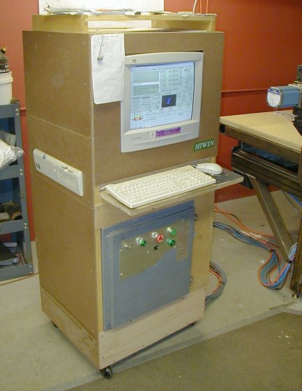
checking). There are always some "pulse quickening" episodes even when things are hooked up correctly but somehow things do not want to move. This happened when I wired the drives and motor, turned the power on, reset Mach2 and pressed the keyboard jog key for the very first time and - nothing. What the hell did I do now? Well, the motor was moving but sooo slowly that I did not notice the motion and it took full 2 minutes of frantic searching for problems before I noticed the turning of the shaft. The "motor tuning" in Mach2 solved the problem. This is a mobile console for the machine controller, 17" monitor and two computers. It can be wheeled around the machine for easy job setup, z zeroing, troubleshooting etc... This is very helpful without an extra pair of hands to help when working on a machine this size. The computers are networked together with crossover network cable and KVM switch. The slower computer which I got for $50 from Ebay (400MHz, 198Meg RAM, Dell Optiplex 110, Windblows 2000pro, Gforce 64meg video card) is mostly dedicated to running Mach2, some CAD/ CAM software and also for data storage on a separate partition. It is running only barebones with 13 processes to maintain clean pulse stream. CAD/CAM application are very modular and do not interfere with the pulsing of the windows timer when they do not run. Screen savers, task schedulers, virus scans and unneeded background processes on the other hand must be eliminated if you want reliable CNC control and smooth motion. Go to "services" and msconfig in Windows and cull it out. If you do not know specifically what processes to shut down, there is a file in the Mach2 "files" section that covers the process of making your Mach2 lean and mean by eliminating the unneeded stuff from WinXP but a lot of this also applies to Win 2000. The other computer ($200 Ebay) is a multipartition setup (2.8MHz, 512Meg RAM, Dell GX270 Optiplex P4 with 2000pro, XP and data partition). It serves as a backup and I work on it with CAD/CAM while the other machine runs Mach2. The KVM switch is great at switching the screen, mouse and keyboard control from one computer to the other with a click of a key without disruption of the running of Mach2. This is a huge time saver since you can watch the machine run (many hours sometimes) and optimise the CAM code or whatever on the other computer at the same time. No waiting for Madvac to finish. Surprisingly, KVM does no disrupt the pulse stream to the machine at all. |
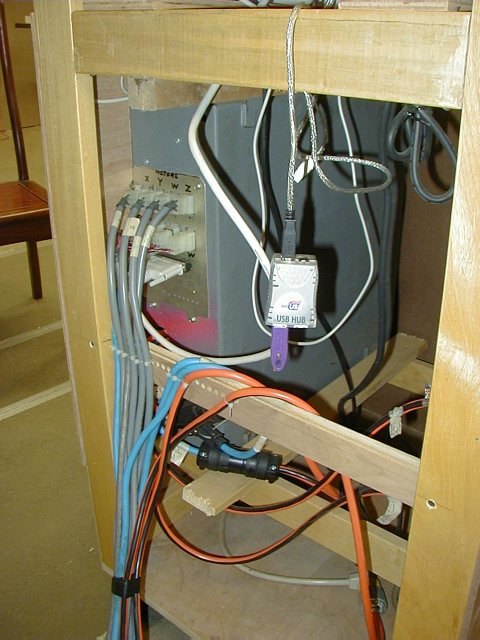 |
Rear
view inside the console. There are two cords supplying power to the computers, controller and the second cord runs the relay operated z router, dust vac and the future W axis spindle (the wiring diagrams show only one 115Vac supply). The top row of the connectors is the power to the motors on all 4 axis. The row below that is all limit switches, e-stop and grounding wire from the machine. Below that is the parallel port hookup from the computer. Further down, not seen are the power cords going out to the spindles and vac. |
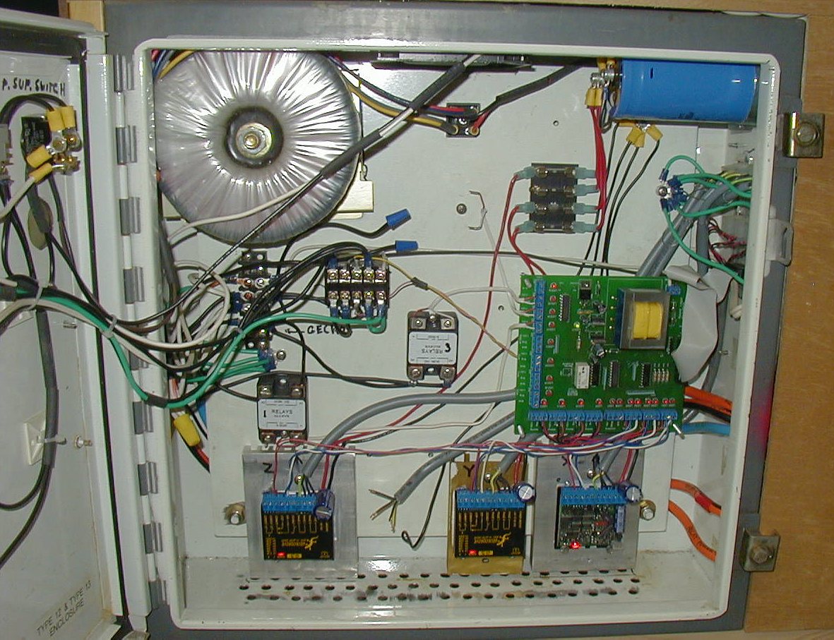 |
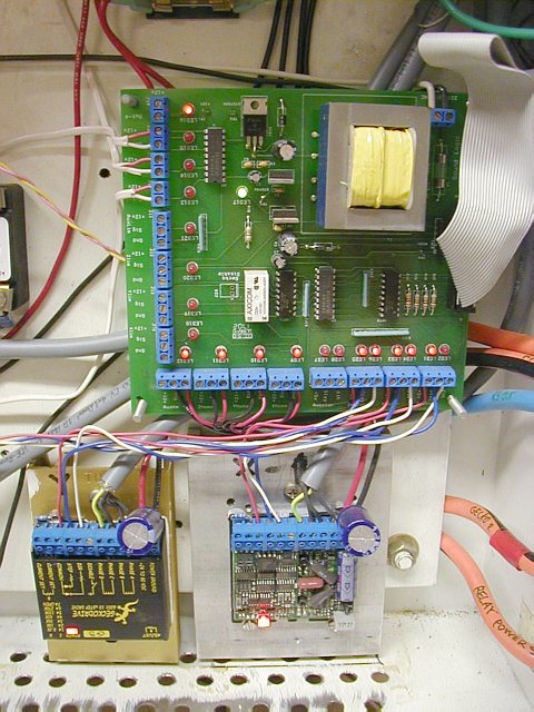
The controller in its full glory. The enclosure is a Hoffman 24"x24"x7"
from Ebay ($50!). I drilled holes at the bottom for cooling air intake and
the exhaust is at top center powered by 115VAC 4"x4" case fan. Starting from the bottom are 2 geckos 201's and one G210 on the right all sitting on heat sinks. These do not even warm up without cooling. Above, right is a Campbell/Cullins breakout board, to the left are two solid state relays and a 4 pole electromechanical relay. Further left is a mess of 115VAC wires coming into out of a connector strip, powering the whole system. Above the breakout board are the power supply components (fuses, capacitor, rectifier, fan and transformer). The total cost of the controller is about $800 - $900. |
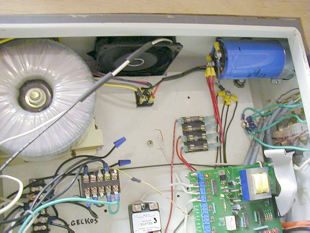 |
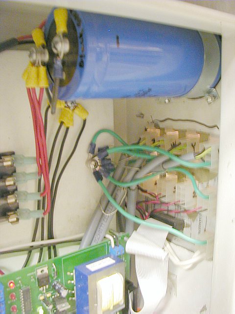
Unregulated Power supply. I got this excellent power supply from Doug Fortune from CNC Kits. It all came prewired with switch, light and fan. It provides 1000Watt at 75VDC and is just about the limit for the 80V max Gecko drives. On the right is the Plitron torroidal transformer taking 120VAC on the primary windings and reducing it to 54VAC on the secondary windings. From there the 54VAC goes to the small square bridge rectifier (center) which outputs 75VDC to the blue capacitor. The capacitor (-) terminal is grounded and the (+) terminal (red wires) go to four 5amp (1.25" x 1/4") fuses. The red wires from the fuses go directly to the Gecko drives. See the circuit diagram. |
 |
The all important "star configuration" grounding pattern. All the cable shields on the machine and the machine ground converge to this single point (green, silver wires) in the controller chassis. The shields on cables must be grounded only at one point otherwise they will create ground loop effect and there will be interference noise messing with your machine. |
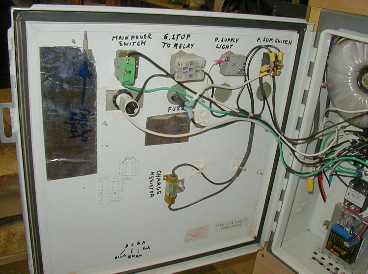 |
The back of the door mounts the system switches, lights, fuse. The wires are hard to trace so it is clarified in the circuit diagram. |
 |
Breakout
board and Geckos below. Strictly speaking, one doesn't need a breakout
board to integrate the parallel port signals into the controller but for
me the board is a vital piece of equipment since it makes wiring very easy,
provides 5VDC to the Geckos, 12VDC to the solid state relays and limit switches,
opto isolates the logic voltage of the computer from the high power of the
other components and the LED lights are nice indicators of the state of
the signals coming from and going to Mach2. The close-up of the breakout board clearly shows how the relays and the Gecko drives are wired from the board. Starting from the top left corner, you can see the three terminal blocks with the red and white wires. These are the 12VDC and ground (com) output lines to the relay coils (router, vac or anything you want). The bottom left corner shows four terminal blocks with red and black wires. These are the home/limit switch loops for all four axes (polarity of wires doesn't matter here for mechanical switches). Both the "home" and "end of travel" limit switches are mounted in series on each circuit. In Mach2 you specify which direction is towards the "home" switch (- -) and which direction is the end of travel switch (++) so that mach2 knows where to home the machine (machine x0,y0,z0,w0). Mechanical limit switches make wiring very simple since two switches on each axis can be lumped into one circuit. With inductive switches for 4 axis machine I believe I would need to wire all 8 blocks in the left low corner of the board with each switch having 3 wires going into the block. The top right corner shows a fat black and white wires which are the 115VAC supply to the board and below is the white ribbon cable which is connected directly to the parallel port of the computer. The bottom right corner shows the thin red, blue and white wires connected to the geckos. The red wire is the +5VDC power to the gecko, the blue is the "step" pulses and the white is the "direction" of the motor turning. The Gecko: The first two contacts are for the current limiting resistor which controls the current into the stepper motor. The value of the resistor is determined by the motor rated current and a formula is in the Gecko manual. Next are the wires I just mentioned. Further right are the four output power wires into the stepper motor. Having a 4 wire bipolar steppers makes wiring very simple (vs the 6 or 8 wire motors). The fat red and black wires are the power supply for the motors coming from the "power supply" capacitor. The small 470uF capacitor between the two wires on the Gecko is to further smooth any ripples (or buffer) voltage from the BIG power supply capacitor . See Gecko manual. That's that. Not very complex. |
|
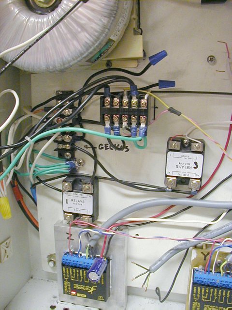
The relay system. The solid state relays (white stickers) are basically
low voltage controlled switches for the router, the dust vac and another
axis router. Each relay takes 12VDC signal from the breakout board and turns
on the relay "coils" which switches on the 115VAC to the router.
In Mach2 you can turn these outputs on or off simply with buttons on the
screen or the M codes (M03, M05, M08 etc..) in your G-code. In Mach2 you need to configure the pins on the parallel port so the right signals are sent to the right places in the breakout board. Since the breakout board is hardwired from the parallel port, the matching of signals (step, direction for motors, relays, spindles etc...) to pins is assigned by the software. One parallel port will provide only enough pins to run 4 motors, have 4 axis worth of limit switch inputs, 3 outputs to relays and couple more signals but that is it. If you need more outputs or inputs you can install a second parallel port which Mach2 supports. This will be my next addition since I need to install a more automated system of zeroing the Z axis but I am out of inputs to the P. port. Of course one needs to add a parallel port PCI card to the computer and some sort of simple buffered breakout board for this to work. The 4 pole relay in the top center is the main AC power distribution switch to the entire machine. See circuit diagram. There are two E-stop switches in the system, one is on the controller door and the other is on the machine. Both switches are wired in series in one circuit as normally closed. The same safety principles apply here as to the limit switches. The circuit is closed (conducts current) under normal operating conditions. If you trip either E switch or if something goes wrong in the wiring, all power is shut off. The E-stop needs to be reset, mach2 needs to be reset and the power-on button pressed to turn the system back on. |
© Copyright
Vaclav Stejskal
All rights reserved
Last page update:
4 May 2005
