 |
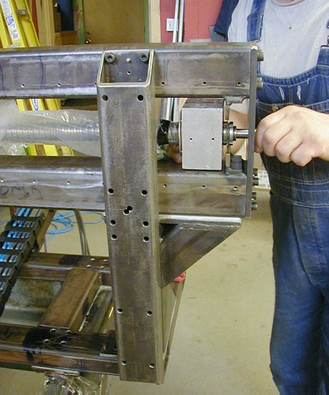
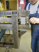
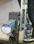
Space is at a premium here so that everything can be compact but also reachable
and maintainable. The plumber block elevation and lateral position was adjusted
from below and the back side with four 10-32 thumb screws so that the travel
of the nut was centered and parallel to the linear slides along the whole
length of travel. Then, epoxy was cast under the block and in the space
of the top and lower metal tabs. Notice the welded tabs behind the plumber
block. The block is fastened by 4 M8 screws through the tabs. The motor
side tabs are permanently welded as you can see and the far side tabs are
removable so that the screw can be inserted and removed. Since everything
is steel, I was not concerned with thermal expansion and screw buckling
between the tab mounts. The fun part is masking, damming and mold releasing
all the separate parts in preparation for the epoxy injections. The final
fit is always perfect! |
 |
|
 |
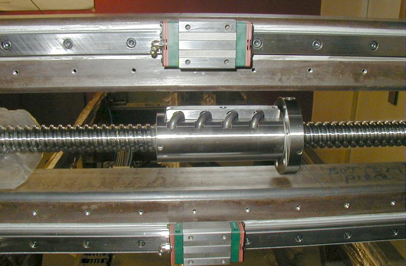
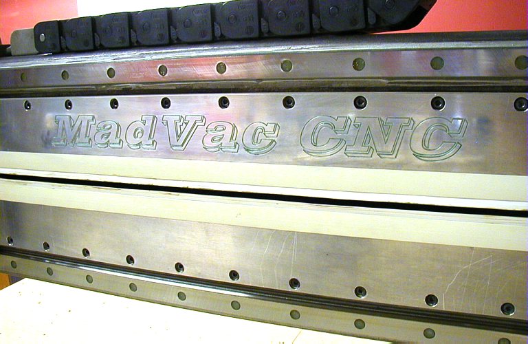
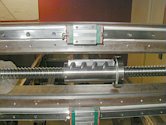
The most time consuming part of the Y gantry design was to consider the
length and centering of all the components so that both Y and W axis would
have largest usable range over the work table and at the same time the slides
would provide a collision buffer before the ball nut would hit the plumber
block at the ends of the travel (without wasting usable length of both components).
The limit switches (not mounted yet) are about 4" in front of the plumber
blocks mounted on an adjustable/sliding tab. Again, this is important so
that you get the maximum usable axis travel without the limit switches imposing
constraints. The switches are operated by a "ramp/cam" welded
to the Y nut yoke. All switch wiring is routed inside the lower Y tubing. |
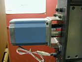 |
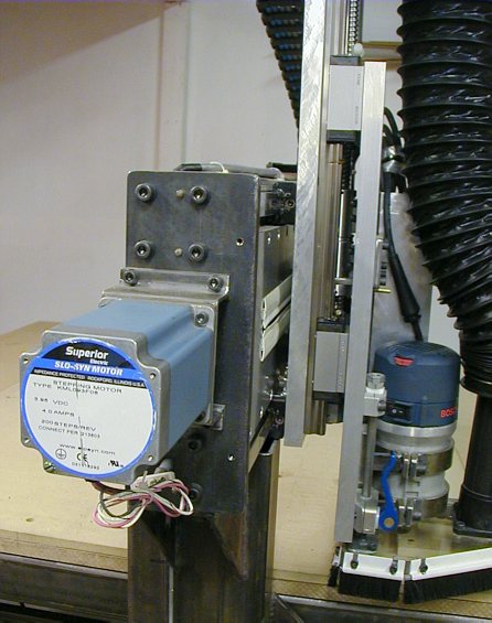
Mounting of the motor is pretty much the same as the X axis. |
|
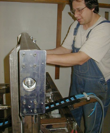
Note
the tapered pins between the end plate screws. This is to guarantee that
the parts will always assemble back together accurately. The pins are made
from soft steel and are disposable after each assembly/ disassembly. |
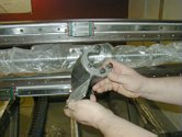 |
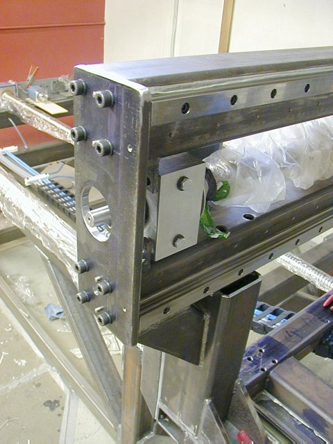
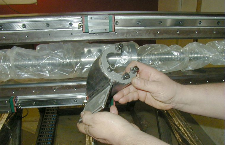
The
Y nut yoke still without the Z axis plate mounting flange. It is removable
from the nut and mounts on the "backside" of the nut flange. This
is generally the mounting side of the ball nut (precision ground for that
purpose). The face of the yoke had to be done like this since the ball recirculation
mechanism on the nut must be on top of the nut otherwise the bearing balls
will not circulate properly. |
 |
The
preload in the nut is achieved by half of the ball grooves in the nut being
ground "offset" so that the balls are compressed against the screw
towards the center of the nut (lengthwise).
Grease - I am using LG-2 Shell Alvania lithium based grease for all the
linear slides, bearings and screws. I called Shell and got a case of 12
large grease tubes for $20 (lifetime supply). This stuff is fairly good.
It is thixotropic and more solid when it sits for a while. After the machine
warm-up movements, it is has far thinner and oily consistency which is great
since it reduces the rolling friction of the bearings considerably. You
can see the difference in the motor stalling at high speeds before and after
warm-up. |
|
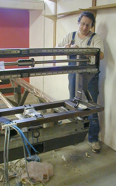
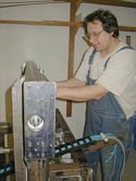
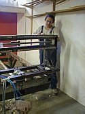
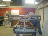
Final adjustments of the far-end block mounting. |
 |
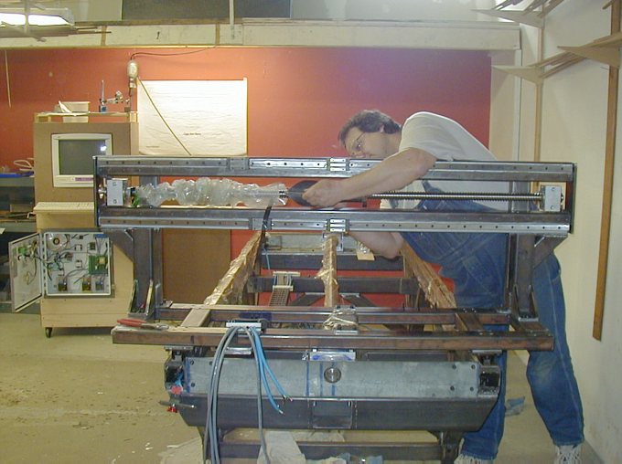
Mounting
Y yoke. |