|
| HOME |
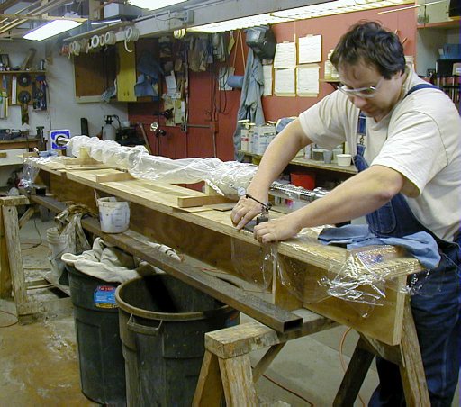 |
Getting ready to install bearings and plumber blocks. This part was the
most interesting process in the machine building experience. I had to wait
for the ball screws for 6 month to arrive. In the meantime, I had some restless
nights thinking about how tight the bearings are going to fit on the shafts
and how to get the plumber blocks and how to make the yoke for the nut to
attach to the gantry so that everything can be adjustable for alignment. The ball nut has zero backlash, 5% preload of the rated axial force which is something on the order of thousands of pounds for this size screw but the movement of the nut is completely smooth and easily turned by hand but with nice stiff feel. The max deviation error on the screw is 0.012mm/300mm. For this type of work you want as little dust around and nice clean clothing and hands. Just one spec of carbide or steel shaving in the nut and there will be problems! Here are the Hiwin specs for all three axes, x, y and z respectively. 1R45 - 10B2 - OFSV - 2690- 2918 - 0.012 Nut - 45-10B2 1R32 - 10B2 - OFSV - 1575 - 1767 - 0.012 Nut- 32-10B2 1R16 - 5B2 - OFSV - 480- 555 - 0.012 Nut - 16-5B2 As a side note, finding a supplier of the ball screws turned out to be a quite exasperating experience. Unlike other industries I have dealt with, this industry seemed to have just about zero interest in getting my business. I have written letters, called, emailed and mostly I got back arrogance, silence or utter disinterest. Getting pricing and reasonable answers was like pulling teeth. THK for example got back to me with cheerful "what can we do for you" 6 months after I had a specific discussion with a rep. at Eastec automation show. Eventually I stumbled over Hiwin and their representative in Chicago who was very helpful in providing quotes and discussing technical issues. So, I got all slides and customized screws from Hiwin (Taiwan). Each screw came with a "ballscrew inspection certificate" and a graph of error tolerances over the whole length of the screw made on German laser measuring system. It is all top quality ground and hardened steel. |
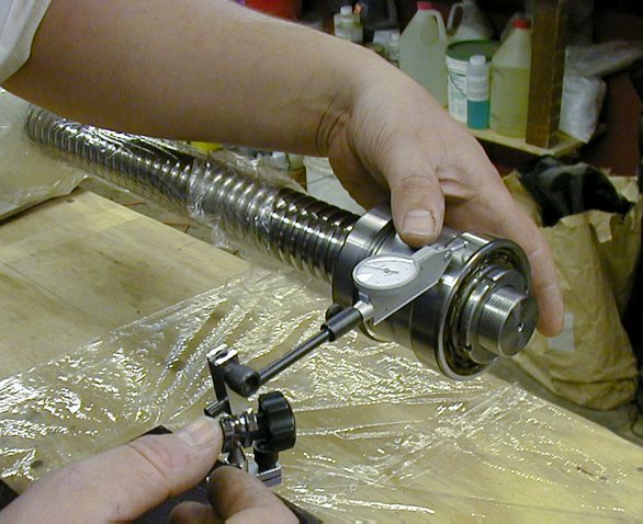 |
My
fears about fitting the bearings proved unfounded. After cleaning the inside
race of the bearing with 1500 grit paper and cleaning up any potential burrs
on the shaft with fine india oil stone, I cleaned and greased the shaft/bearing
lightly and tapped the inner race onto the shaft with a stick of hard wood
and a hammer. Once the whole bearing was 1/4 engaged, it moved quite smoothly
with taps around the perimeter. No heating or special tools were required.
The tolerances on these components are just amazing. What are the tolerances
on the machines that make these parts and their own parts?! The bearings are metric SKF angular contract ABEC 3 (from MSC). Had I gone with ABEC 5 and higher you can expect to pay a couple grand for the bearings alone in this machine. ABEC 3 class stipulates certain runout tolerance in both radial and axial direction but in reality, I believe they are made to be in the "better" range of allowable deviations. Once aligned, I got 0.0001" axial runout and about 0.0002" radial runout and that is probably only because of the poorly machined spacer between the bearings and me having no more patience with alignment. The spacer was the only thing I had to have done through a local machine shop. When I brought this thing home and measured the parallelism with a micrometer, it was off by 0.001". These guys put it on a surface grinder but the cylinder was obviously not fastened to the table properly and one side was not square. So after exclaiming a few words I would not want to repeat here, out came the diamond hone and 800 grit sandpaper and india oil stone to knock down the hump to 0.0001". I could have made these myself as well. Bearing preload principle- The spacer is a cylinder with parallel faces that press against the outer races of the bearings. When you tighten the shaft locking nut, the nut presses against the inner race (#1 bearing) which pushes the balls which press against the outer race #1 which pushes the spacer which presses the outer race (#2 bearing) which pushes against the balls, which push the inner race#2 which presses against the shoulder of the ball screw. This is how the bearings achieve preload in my particular setup. After the shaft nut comes a spring washer and another nut to compress the washer between the nuts. The large space between the bearings makes the seating of the bearings in the plumber block very rigid and resistant to bending moments, thus it is called "fixed" arrangement. I naively assumed that the bearings would come "preloaded" by themselves. What a surprise to see the inner and outer races just loosely floating around. This feature is only available for the very expensive double row bearings. So, the alignment is done by tightening the shaft nut by hand and rotating the assembly, tapping things into position so that the bearings and the spacer have the smallest radial runout. You tap, spin, measure, tap, rotate, measure, tighten, rotate....until the eyes are blurry! With 4 bearings on the screw, the axial error seems to be averaged out to almost nothing as far as my accuracy needs are concerned. |
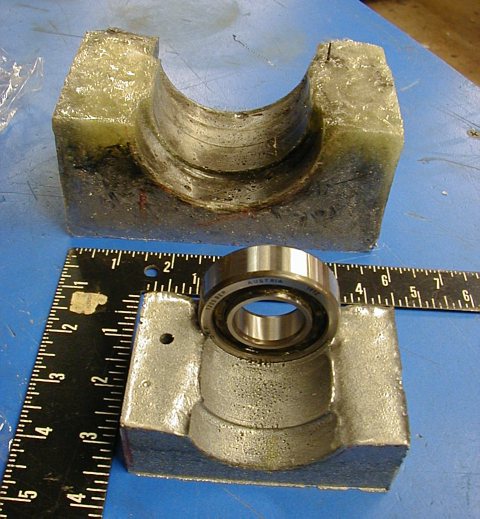 |
First major failure (dead end) due to wrong material but the concept is
sound and this is essentially how the insides of the working plumber blocks
look like. These are chopped fiber epoxy casts poured into a mold built around the bearings on the screw shaft. The major flaw of this process is the epoxy exotherm which brought this volume of liquid epoxy to a steaming mass and boiling point right on the shaft and around the bearings! I was freaking out realizing that this might affect the temper of the ball screw and the bearings. There was little to do except to run around this mess with a wet sponge cooling it until the worst temps were over (like a scene from 3 stooges). Needless to say, these casting were full of bubbles and completely distorted unusable junk. There goes 60 bucks of epoxy and more $$ of cleanup time. Then I realized, why not make the whole thing from big aluminum blocks (Admiral metals outlet) and leave only small 1/4" concentric space around the bearings and mating surfaces for casting the epoxy. I would need only about 60ml of epoxy and the metal is a perfect heat sink (the epoxy is filled with aluminum and stainless steel powder) That is how the blocks were made and the fit around the bearings is completely air tight. The entire axial force of the x axis movement is supported by the "epoxy ridge" between the outer bearing races in each plumber block. |
|
Here
is the progression of the aluminum block to the finish. The actual size
of the x block is 150mm x 146mm x 78mm. If you are going to hack you plumber
blocks form one piece of metal like I did, it is important to start with
a block that has at least 3 faces nicely orthogonal to each other so that
you can scribe the block with accurate lines on both sides and it can be
setup nicely for casting. This block is too thick for any conventional drill
to go all the way through, so I had to drill from both sides. First, the
hole for the bearing was drilled out along the perimeter (see Block 1) and
then I used hand drill mounted "hole saw" that plumbers use to
drill through wood joists. Here I had to finish cutting all the way through
from both sides barely meeting in the middle. The hole is filed reasonably
smooth but it must stay coarse so that the epoxy pour will have a good mechanical
bond. Block 2 is split with about 4mm gap. Both the top and lower half of the block must seat together precisely so the joint has to have cast surfaces too. The lower surface/parting line is in the same plane as the shaft axis so that block comes off the bearing after casting. Block 3 aligned for casting. It is sitting on glass plate aligned from below with thumb screws to get the base exactly parallel to the screw and at exact height between the bearing and the plate. I used parallels for the bearing to plate gap setting), Front face of blocks aligned with face of bearing. Lower block is hot glued in position. Top block sits on 4mm spacers in the gap. While the squares are clamped to the blocks, all gaps between the bearing and the block are taped over with clear packing tape and in corners (see arrow point 2 in lower drawing) reinforced with aluminum tape. This will hold the blocks in nice alignment. Arrows #3 point to 2 vent holes to vent displaced air as the epoxy is injected in the cavity. Point 1 is the lowest point of injection. I calculated the volume of epoxy needed from the cad drawing. Block 4 is what the entire block looks like finished with nicely molded bearing seats. The drawing is only schematic since the lower half had to be cast first with the parting suface waxed and mold relased! |
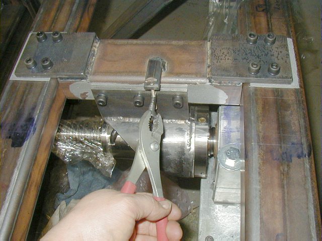  |
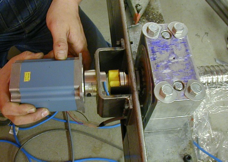
The ball nut elevation can be adjusted and was very helpful in aligning
the plumber blocks. The axis of the screw has the same elevation in the
blocks and the nut with respect to the linear slides. Note all the "squared"
epoxy cast mating surfaces (gray color). The yoke for the nut is made from 5"dia steel pipe and some flat plate. It is all tig welded together. All the mating surfaces are aluminized epoxy squared to each other. This is where parallels, squares and a flat granite plate (or good quality thick glass plate) are very helpful in setup and casting the epoxy. |
 |
The
triple stack bipolar NEMA 34 steppers (1100oz-in) are real work horses!
In testing I was able to get the gantry to 170"/min max speed in places
before stalling. You cannot just run normal operations at this speed because
there is very little guarantee that you do not lose steps or stall the motors.
To get a good assurance of repeatability, it is important to derate the
max operating jog speed by about 30%+. I have set the X axis max jog rate
at 118 in/min to be well inside the margin of reliability and at this speed
the steppers never stall or lose steps. It is still perfectly fast enough
for all my needs. The beauty of steppers is that all milling is done at
low speeds where the motor is the strongest and very reliable. It is the
fast jogging you should worry about. If stepper motors stall at low speeds,
they are too weak for the application, the power supply may be insufficient
or the mechanics of the machine are not smooth. The motor is high torque KML093F08 and I got these new from a place (Electro sales) just 5 minutes from my shop! The cost of brand new motor at the time $290. The stepper is connected directly to the ballscrew and is able to move this mass to speeds of 156 in/min (396 rev/min). At this speed and lower torque output, there is one "node" at the end of the x axis where the resonant frequency of the ballscrew will eventually stall the motor. Fortunately, this is one spot where the gantry spends almost no time and the situation has an ultimate solution by lowering the speeds or if needed by replacing the stepper with a "vibration reduced" servo motor. At 120in/min I am physically unable to stall the motor - the gantry will drag my 250lb butt on the floor no matter how much I dig in my heels. Given the torque/speed curve of steppers, any movement under 100in/min happens with bone crushing force of hundreds of pounds and I cringe to think about the force at normal feed rates. You would not want to forget your little fingers on the frame while the gantry is passing by. Once I forgot where the Z zero was and plunged a nonrotating 1/2" end mill straight through 1.5" thick particleboard at 45in/min like a needle into pudding until a limit switch stopped it. Only then one begins to realize the "malevolent side" of one's creation ;) Most of my feed speeds for wood and plastic routing are up to 46in/min and for aluminum to 24in/min with 1/4" mill so the machine has plenty reserve strength and speed and the motors never lose steps. Also, with stepper motors, you do not want to whip the machine back and forth at high speed/accelerations since steppers are open loop system and there is no feedback to see if they lost steps during the cutting. Only an inaccurate scrap part will show what happened or you have to watch it like a hawk as it cuts. With servos, one can push the performance envelope but with steppers, you want to have a good 25 - 40% margin of safety when it comes to fast jogs (non cutting tool positioning movement at highest speed settings) or feed rates. |
 |
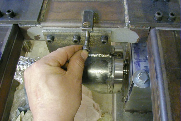
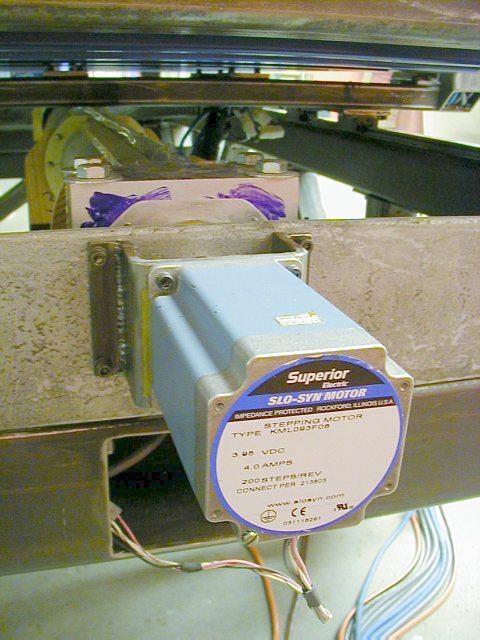
Here
you can see the block bolted down to its cast bed with 1/2" x 8"
bolts. The smaller 5/16" bolts hold the plumber block halves together
and the bearings in tight grip. Here is another example of the necessity for early planning. I was looking at potential candidates for motor to shaft couplings and the "jaw" (spider) coupling (MSC) was ideal, however, the mating parts have only limited range of shaft diamters. My "potential" motors had 1/2" shaft so the best shaft diameter of the ball screw was 5/8". 3/4" would be too much for finding couplings and potential servo pulleys. 1/2" would be too small and potentially small for this size ballscrew and 3/8" on a screw of this diameter would be a really bad choice. With 5/8" you can still find good range of couplings, shaft extensions and timing belt pulleys for servos. The jaw couplings are excellent since they are zero backlash, tolerate some axial and some radial misalignment, are made modular with different shaft size matches. They clamp the shaft rather then damaging it with a set screw and least but not last, they dampen some vibration and the polyurethane spiders are available in two "hardnesses". The yellow is softer. Speaking of vibration, a stepper CNC machine is pretty much like one big VIBRATION tuning fork so you have to take care to consider stiffness, resonance and damping in every part. It is enough to have three Nema 34 stepper motors singing a symphony of simultaneous acceleration/ deceleration vibration tunes, add to that the vibration/chatter of a routing bit, the buffeting of vacuum system air flow, the clatter of recirculating bearings, rapid changing of direction of the moving machinery parts and on top of that add an unballanced screaming router as your spindle. It is just astonishing that the stepper motors can take this abuse without loosing steps. Let me state plainly that even the smoothest wood router SUCKS as a CNC spindle and I believe I have one of the smoother ones (a new 2.25Hp Bosch 1775). On a precision CNC machine, the vibration of its unbalanced rotor and windings at any RPM will downgrade the machine performance and it will even stall the steppers under some conditions/ RPM's not to mention the irritation of listening to hours of continuous 90dB noise. The problem is that a router is a $300 item and to cut vibration, the next step up is a high speed air spindle at $500+ (not counting the huge volume compressor, coalescing filter and cost of air at 9 times of electricity) and then we are talking $3000+ on the low end for a 3 phase 220V Colombo or Perske spindle with AC frequency (VFD) drive. One way or another, this will be my next mandatory upgrade because I hate to see what the router is doing to the ballscrews and the linear slides and the noise is miserable even at "quiet" 8000 RPM". A wood router on a machine with class C ground ball screws and linear slides is like like a Porsche with wooden wheels and a cable spool for a seat. Other than that, mechanically I would change very little since the machine has exceeded my expectations in many ways. It is strong, relatively fast for my needs (limited by steppers and drives) and all the movement is smooth on all axis and most importantly, it is beautifully accurate. |
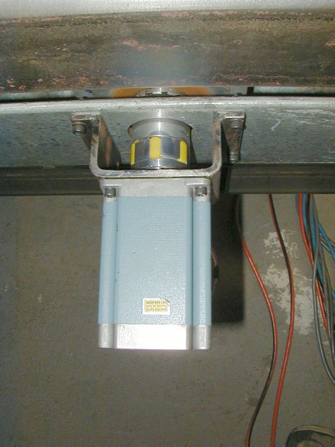 |
If
you can help it, get the "clamp" style rather than set screw types
of couplings. Much better grip, no damage to the shaft. Note the handmade yellow polyurethane bearing seals on the end of the block. The angular contact bearings have no shields so this is the only barrier to contamination and to keep the grease in the bearings/blocks.. |
|
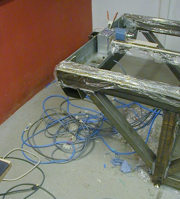
Wiring madness and motor tuning before mounting. |
© Copyright
Vaclav Stejskal
All rights reserved
Last page update:
19 October 2004